
Transformers
Different things need different amounts of energy; you wouldn't try to use the potential energy in an elastic band to move a bus, or the kinetic energy of a race car to juice an orange! Just like mechanical things, electrical things need specific amounts of energy provided in a specific way so that they work properly (Pisupati 2018). Transformers 'transform' electrical energy so that it can be used by devices, like your phone or clock (Pisupati 2018).
What is Electricity?
On The 'Electro' Part page, you discovered that electricity is the movement of charge (the movement of electrons to be specific), but to understand how to use electricity, and why different electrical devices need different amounts of electricity, we need to understand how charge moves.
This cable helps you visuallise the movement of charge from the power outlet to the phone - just remember that you're not actually seeing real charged particles move! Image: (Odditymall 2017).
Where Does Charge Come From and How Does It Move?
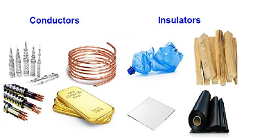
All metals are conductors, but most non-metals are insulators (Fitzpatrick 2007). Image: (Byju's 2016).
Power lines and electrical wires carry electricity, so they carry moving charge - but where does the charge come from? When electricity moves, tiny charged things don't just spontaneously appear. You already learnt that everything is made of tiny charged particles on The 'Electro' Part page; a special negatively charged particle that all materials (even you) have in them is called an electron (Northwestern University 2001). Electrons are special because, in certain materials, they are able to move around, so, electricity is the movement of electrons (Northwestern University 2001). We call materials that allow electrons to 'flow' through them conductors of electricity because they allow electricity to 'move' through them (Fitzpatrick 2007). Materials that don't allow electrons to 'move' through them are called insulators, because they don't allow electricity to 'flow' through them (Fitzpatrick 2007).
But I Thought That Electrons Were 'Stuck' To Atoms
Not completely. You're right in thinking that atoms need electrons, because they need to balance the positive charge of their nuclei, so that they have no overall charge (ask your teacher about the atom if you're confused; The University of California, Berkeley 2013). In conductors (that are electrically neutral), electrons still balance the charge of all the nuclei that are 'stuck' together, but they are able to move between the atoms (Baragiola 2002). In metals structures (which are all conductors of electricity), the electrons that are 'furthest' away from each of the atoms (the outter shell electrons, for year 10's) are able to move throughout the entire metal - we call these delocalised electrons, because they don't need to stay around any one atom (Baragiola 2002).
When metals 'bond'(stick) together, the electrons furthest away from each of the atoms are free to move around the entire lattice (metal structure; The British Broadcasting Corporation 2014). Sometimes we call these a sea of delocalised electrons (The British Broadcasting Corporation 2014).
Wouldn't All The Electrons Get Stuck At One Side?

Diagram of an electrical circuit (Wiki Kids Ltd). Note that all the switch does to stop the electricity flowing is 'break' the loop (The University of California, Davis 2001).
Yes, if electrons were flowing in one direction (which they must) through a wire that isn't a loop, they'd start collecting at the end (Hughes 2005). But this can't happen for ever, conductors only have a certain number of electrons that are able to move around (Hughes 2005). Also, when things of like charge collect together, they repel each other, so it wouldn't take very long for charge to stop flowing, because this force of electrostatic repulsion would balance the force making the electrons flow (Fitzpatrick 2007).
Batteries overcome this issue, by using special chemical reactions at the negative terminal (the half of the battery with a minus sign on it) that reorganize atoms to 'give off' electrons, and other chemical reactions at the positive terminal (the half of the battery with the plus sign on it) to put these electrons into other substances (Washington University in St Louis 2005). In batteries, the build-up of electrons at the negative terminal pushes them towards the positive terminal, where they don't 'build-up' because they are used in making other substances (Washington University in St Louis 2005). However, we don't use batteries to make most of our electricity (The Australian Government 2016).
So How Can We Make Electrons Move?
You already know that like charges repel, opposite charges attract and electricity is generally the movement of electrons, which have a negative charge (Fitzpatrick 2007). So, if we can't move positive charge easily (and pull the electrons to where we want them to go), then we have to push the electrons (Fitzpatrick 2007). Imagine if we just pushed a few, in a specific area of a wire that was in a loop - what would happen? We would end up pushing these electrons closer to other electrons, then the force of repulsion between like-charges (the force that pushes things with the same charge away from each other) would push the other charges, which would then push more charges until all the electrons in the loop of wire were moving (The University of California, Davis 2001). If this doesn't make a lot of sense, imagine standing up a set of dominoes in a line and pushing one over, each domino would fall onto the next in a chain reaction.
Dominoes Chain Reaction (Gifer 2018).

The changing magnetic field of an electromagnet under the magnetic fluid (ferrofluid) in this GIF makes the fluid change into different shapes (Hussaini 2017).
So Do We Push Electrons With Our Hands?
No, that'd be very hard. We already know that magnetic things can push and pull other magnetic things, and that electric charges have magnetic fields when they're moving - but what about when they're not moving? If we keep changing the strength or direction of a magnetic field, it's like the charge is moving from the perspective of the magnetic field (Liao et al. 2004). So, a magnetic field that's changing in direction or strength will push or pull an electric charge (like an electron) (Liao et al. 2004). This means that if we create a changing magnetic field near something that conducts electricity (like a wire) we can induce (create) the flow of charge in that wire, without actually touching it (Liao et al. 2004)!
How Do We Measure The Movement of Electrons?
Have you ever seen a sign displaying the words 'high voltage'? We measure the amount of energy we give electrons as voltage or electromotive force - this just tells us the amount of energy that we're giving to each charge (Nave 2017). We measure voltage in volts (V) (Nave 2017). As changing magnetic fields can 'push' or 'pull' electrons (exert a force on them), we say that they can induce voltage (create voltage or EMF in something; Dux College 2015). We also measure the flow of charge, and we call this measurement electric current (Davis 2011). Current is the amount of charge that passes a point in a wire (or other conductor) in one second, so it can be used to tell us how quickly charge moves through a wire (Davis 2011). We measure current in Amperes, or Amps (A) (Nave 2017).

High-Voltage Warning Sign (Takken 2016).
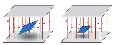
Imagine that the perimeter of the blue rectangle is a wire - the magnetic flux is the blue area area surrounded by the wire (Khan Academy 2018). The red lines indicate the magnetic field (sometimes called B), and its direction. Notice how the magnetic flux in the wire gets smaller the closer the wire loop gets to being parallel with the magnetic field (when it would be zero; Khan Academy 2018).
How Do We Measure The Amount of 'Magnetic Field' Going Through Something?
If we want to know how much a magnetic field that's going through an object has changed, we need to be able to measure how much of the magnetic field is a specific area (Nave 2017). We call the 'amount' of a magnetic field in an area magnetic flux, and we call the strength of a magnetic field in a certain area magnetic flux density, because density tells us how something is spread in an area (Dux College 2015). We measure magnetic flux in Webers (Wb), and magnetic flux denisty in Webers per square meter (Wb m ) (Nave 2017). So, changing the strength of a magnetic field changes the amount of magnetic flux through a certain area, which can induce voltage (exert a force on electrons), if a conductor happens to be in that area (Dux College 2015). When we're trying to induce voltage in a wire, the only magnetic flux that matters is the magnetic flux in the area surrounded by the wire (Dux College 2015).
-2
What If A Wire Is Coiled?
If a wire is coiled, more magnetic flux 'links' it (while only taking up a small 'area'), so a greater voltage is induced (Dux College 2015). We call wire coils that are designed to have voltage induced in them, or designed to create a magnetic field when electricity flows through them solenoids (Richmond 2001). As the magnet on the right moves, the magnetic flux in the solenoid changes, causing it to induce voltage. As the rate of change (how quickly it changes) of magnetic flux 'inside' the solenoid increases as the speed of the magnet increases, the voltage induced increases as the speed of the magnet increases (Richmond 2001).
'
Diagram of a moving magnet inducing electromotive force in a solenoid (Marshall 2016). Note that the thing that measures the voltage is called a voltmeter (Kenyon College 2002).
How Can I Work Out What Direction The Charges Will Be Pushed?
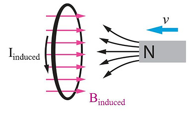
Lenz' s Law Diagram (Perry 2016). Note that I represents current, B represents a magnetic field and V represents the direction of movement of the magnet.
You already know that moving charges have the own magnetic fields, and the direction of the magnetic field that a moving that a moving charge makes depends on the direction that it's moving (we can work it out using the right hand grip rule, and pointing our thumb in the direction of positive charge movement; Fitzpatrick 2007). In the GIF above, imagine that the movement of the charge in the wire creates a magnetic field that goes in the same direction as the magnetic field created by the magnet. This would mean that the wire would pull the magnet to the right, making it go faster, which would, in turn, make the magnetic field in the wire stronger, which would make the magnet go faster (Luna 2011)! Obviously, this can't happen because we'd be creating more and more energy from nothing, so the setup would be violating the conservation of energy (which you should have learnt about since year 7; Luna 2011). This means that changing magnetic fields must induce currents (electron movement) that have magnetic fields that oppose the magnetic field that created them (Luna 2011). In the image above, this means that the solenoid's magnetic field will push the magnetic in the opposite direction to the way it's moving - it'll try to slow it down (Luna 2011). We call this Lenz's Law (Luna 2011).
Lenz's Law states that a current induced by a changing magnetic field will flow so its magnetic field opposes the change in magnetic flux inside it (Sevian 1998).
How Can We Create a Changing Magnetic Field With An Electromagnet?
We know that the strength of a magnetic field created by an electric current increases as the electric current (movement of the charges) increases. So, if we keep changing an electric current flowing through a wire, the magnetic field around it will also keep changing (Dux College 2015). This can be used to induce an electric current in wires that are close by (Dux College 2015). The electricity that you get from power outlets (the things you can plug devices into in the wall) and power lines is a special 'type' of electric current that's constantly changing, called Alternating Current (AC) (Sevian 2000). This changes direction 100 times in a second (Sevian 2000). If we make an alternating current in a wire, it will have a changing magnetic field (Sevian 2000).
Diagram of Alternating Current in a Circuit (Daware 2015).
Graph of The Voltage of an Alternating Current

Graph of the voltage of an AC electric current vs. Time (Wavelength Electronics, Inc 2017).
So How Does a Transformer Work?
All transformers have at least two coils of wire (some can have multiple secondary coils), a primary coil and a secondary coil (Dux College 2015). Alternating voltage (an alternating current) is applied to the primary coil (we attach a power source to the primary coil), and the secondary coil makes an electrical circuit without a power supply (there's nothing in the secondary circuit that provides voltage, except the transformer; Calvert 2015). Both of these are insulated (the wires are coated in an insulator, like plastic, that stops them from conducting between coils, so the electrons are forced to go all the way through each coil) and wound (rapped) around opposite ends of a core that's usually made of iron (Calvert 2015). As alternating currents create changing magnetic fields, the magnetic flux 'inside' the secondary coil changes, inducing voltage in the secondary coil (Calvert 2015). We call this phenomenon (creating an electromotive force in something using an electric current, without touching it) mutual induction (Calvert 2015). You should also note that in some transformers, one coil is placed inside the other, and the core is placed in the middle (Champion et al. 2015).
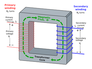
Transformer Diagram (Swafford 2016).
This is the equation for finding the voltage of the secondary coil of a transformer (Nave 2017). V represents voltage and N represents the number of loops in a coil (Nave 2017). P and S represent the primary and secondary coils, respectively (Nave 2017). For example, V is the voltage of the secondary coil (Nave 2017).
=
V N
V N
p
p
S
S
- -
In an ideal transformer (one that works perfectly without losing any energy), the voltage induced in the secondary coil by the magnetic field of the primary coil depends on the ratio of loops (complete circles) in each coil (Calvert 2015). If the ratio of loops in the primary coil to loops in the secondary coil is 1:1 (remember ratios from year 7 maths), the voltage induced in the secondary coil will be the same as the voltage in the primary coil (Calvert 2015). If the ratio is 1:2, the voltage induced in the secondary coil will be twice the voltage in the primary coil; this is called a step-up transformer, because the voltage in the secondary coil is higher than the voltage in the primary coil (Duffy 2000). If the ratio was 2:1, the voltage induced in the secondary coil would be half the voltage in the primary coil; this is called a step-down transformer, because the voltage in the secondary coil is less than the voltage in the primary coil (Duffy 2000). Even though step-up transformers produce a voltage that's larger than the supply voltage, they don't give the secondary coil more power than the primary coil (this would be a violation of the conservation of energy; Champion et al. 2015). In step-up transformers, even though the charges (electrons) in the secondary coil are given more energy than the charges in the primary coil, they move slower - this means that energy is conserved (Champion et al. 2015).
Why DO Transformers Have Cores?
As the amount of magnetic flux decreases the further away we are from the source of the magnetic field (because the field strength decreases), the amount by which it changes also decreases (Calvert 2015). So, ideally, we want the two coils of a transformer really close to each other so the magnetic flux inside the secondary coil changes just as much as the magnetic flux inside the primary coil (Champion et al. 2015). If we could increase the strength of the magnetic field, we could make the transformer more efficient because more of the flux produced by the primary coil would be inside the secondary coil (Champion et al. 2015). This is what a core does (Champion et al. 2015). Cores are made out of soft magnets that align their magnetic fields with the magnetic field created by the primary coil - making it stronger, and increasing the efficiency of the transformer (how close the predicted voltage in the secondary coil is to the real voltage induced; Calvert 2015).
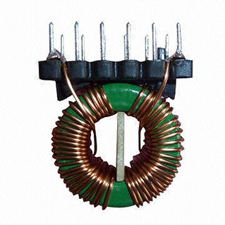
Some transformers have toroidal cores (cores in the shape of circles) because they increase efficiency Sullivan et al. 2007).
Laminated Rectangular Transformer Core Diagram (Faizan n.d.).
What is a Non-Ideal Transformer
Any real transformer doesn't work ideally because some energy is always lost (Calvert 2015). In any wire (that's not a superconductor, see the Magnetic Levitation Page), there's always some resistance - something slowing down the movement of electrons (Champion et al. 2015). This is because there are other things in the wire that electrons collide with, and 'give' some of their energy to (Champion et al. 2015). This energy is using transformed into heat energy (Champion et al. 2015). Currents can also be induced in other conductors that are nearby, including the transformer core (Calvert 2015). These currents are called eddy currents or stray losses (Calvert 2015). Most transformers have laminated cores (cores made of lots of little layers that are laminated, to stop electricity flowing between them), to stop big eddy currents forming (Champion et al. 2015). Ferromagnetic materials, like transformer cores, also change their shapes slightly when they are magnetised, which also uses energy - this is called magnetostriction, and is why some transformers make buzzing sounds (Nave 2017). Also, it takes some energy to change the direction of the magnetic fields of electrons in the core - this is called hysteresis loss (Calvert 2015).